|
|||||||
| Register | FAQ | Members List | Calendar | Today's Posts | Search |
 |
|
|
Thread Tools | Rate Thread | Display Modes |
|
|
|
#1
|
||||
|
||||
|
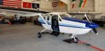
pictures
Hopefully these photos illustrates the issue graphically. The mount halves are designed to meet using a 0.620" spacer between them but my (our?) spacers are 0.770" thick leaving a 0.150" gap that cannot be made up. This issue also translates to the internal spacer which defines the amount of compression preload. Its length is designed to permit 0.410" of compression but because the mount halves never meet one would have to compress the mount 0.560" to tighten, a distance that cannot be realized with the length of threads available and is 37% greater than intended. As is, the mount never becomes a unified, stressed assembly as designed. The engine is just hanging off the upper mount half.
The thickness of the engine mount spacer, not including the flange which extends through the mounting plate, is compatible with the 0.310" flange of the two shock mount halves. I'm beginning to believe that the part was never designed correctly by Cessna and that this issue has existed from birth. Hard to fathom but I have no other explanation. 
|
|
#3
 09-11-22, 11:28 PM
|
|||
|
|||
|
Ive changed many Skymaster engines over the years and I know they can be a pain.
Get your parts book and make sure your hardware is correct for each corner. The p/n for the mount is correct and they dont touch each other in the middle of the mount.
|
|
#4
09-12-22, 11:58 AM
|
||||
|
||||
|
I briefly considered altering the engine mount spacer but that would change the entire dynafocal geometry. Wasn't willing to go there. A work-around that I do believe has merit is to add a spacer to close the gap between shock mount halves and to add a like length to the internal spacer through the use of standard flat washers. This is obviously an "extrajudicial" solution and therefore "experimental". See attached photos.
Although I respect the considerable experience Kim has with these aircraft I do not understand his comments. The exact mounting hardware used is not relevant to this discussion. And his contention that the shock mount halves do not meet in the middle is just a restatement of exactly the problem, they are supposed to meet. Their meeting is necessary to carry the load across the entire cross-section of the mount and into the lower mount half and even more importantly the length of the internal spacer is predicated on that relationship. As is the internal spacer is just rattling about doing nothing.
|
|
#5
09-12-22, 03:17 PM
|
|||
|
|||
|
If you have a parts manual use the hardware stack as show if the nut bottoms out on the bolt before the mount halves have contacted the internal space then add a washer under the nut and again the mount halves do not contact each other inside the mount if they do the mounts will be able to move inside the engine mount frame and thats not good.
Ive done 24 in the last few years. I do know how they go I dont mean to be snarky, I want to make sure you get it right
|
|
#6
09-13-22, 01:36 PM
|
||||
|
||||
|
Kim, I appreciate your taking the time to consider this situation and for all that you
contribute to this forum. A well reasoned argument is never snarky and would never be taken as such. We are both trying to achieve the same ends; to realize a shock mount installation that is in conformance with its design intentions and is performing optimally. However, please indulge my continued skepticism the reasons for which I shall endeavor to set forth as follows: Firstly, yes, if the mount halves were to make contact with one another grossly in advance of contacting the engine mount spacer it is conceivable that the assembly could fail to achieve unity however these parts are designed and manufactured to close tolerances. The outside diameter of the mount flanges are just a sliding fit within the inside diameter of the engine mount spacer. When the assembly is drawn together using a 7/16 diameter fastener tightened to 40 lb-ft of torque a tremendous clamping force is achieved unifying the component parts in tension along their mating surfaces. Theyre not going anywhere. Secondly, I have attached hereto Lord Engineering drawing no. S-6493 detailing the design installation configuration for the J-9613-31 mounting kit and its component parts. I would draw your attention to the cross-sectional view in the upper right hand corner which depicts a single mating line through the forward and reverse Cs of the metallic shoulder and flange of the mount halves. There is no double line indicating the intention of a gap of 0.15 or of any similar magnitude. Also, please note the dimension of 0.62 across the mouth of the C's. In other words a dimension of 0.31 as being the flange height of each mount half. These values can be confirmed by measurement of the actual part. In short, this manufacturers technical drawing conclusively depicts the installed shock mount halves are intended to mate upon assembly. Thirdly, with respect to achieving the proper preload compression using an AN7 bolt, this is the issue which started this whole critical investigation. The internal length of the mated, uncompressed mount halves minus the length of the internal spacer is 0.41. This dimension could be called the compression distance. When the mount halves are separated by 0.15 this compression distance increases to 0.56. The length of threads on this bolt is somewhat variable depending a manufacturer but is generally between 0.5 and 0.6. On the new hardware purchased for this installation the thread length measured approximately 0.5. Subtracting 0.1 to allow the nut to be started on the first full turn of thread leaves 0.4 to 0.5 of thread available to do useful work. This is marginally sufficient to accomplish 0.41 of compression distance in the mated configuration but is wholly inadequate to realize the 0.56 of compression distance which would be required to achieve capturing the internal spacer in the gap configuration. And, if one had a fastener of sufficient thread length to realize the mating of the upper and lower mount halves with the internal spacer, the resulting compression of the mount would be some 37% greater than the design intention. This significantly stiffens the assembly ( degrades its elasticity ) and compromises its ability to capture and isolate vibration passing into it. I find the forgoing compelling evidence to conclude that these mounts, as employed in this application, fail to conform to their approved design criteria and are performing less than optimally. If you have access to data which allows for a reasonable alternative conclusion I would be most interested in considering same. Sometimes the facts that we are most sure of are the same facts that contain the greatest error.
|


 Hybrid Mode
